
Cam Sensor Wiring Diagram
Cam Sensor Wiring Diagram - Incorrect wiring will damage the sensor. It generates a digital frequency as the windows and targets in the. Does anybody know which wire color goes where? This type of wiring diagram reveals all of the necessary information on how to splice, supply power, and ground each component. There are two types of camshaft position sensors, one has two wires known as magnetic or inductive type camshaft position sensor and the other has three wires known as hall effect camshaft position sensor. Web so i screwed up when i was changing the coils and spark plugs and tore out all three wires from the camshaft position sensor connector (vvt sensor bank 1 exhaust) on the rear engine.
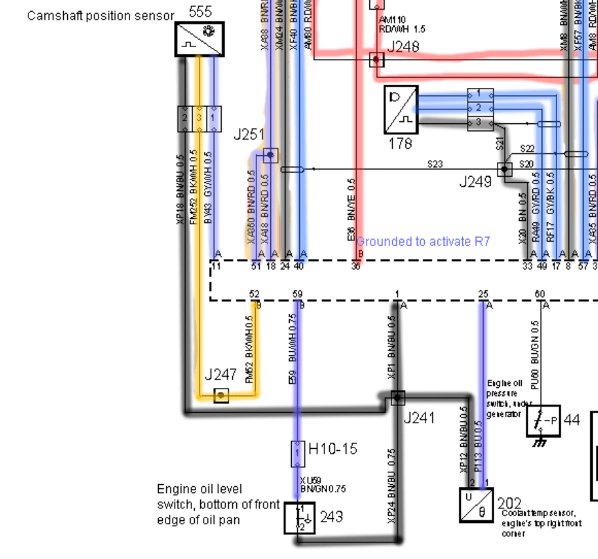
Any helpful suggestion, comments or wire diagrams are appreciated. When the engine is running, the gap between the. Web can anyone who drivers a 2005 ford f150 fx4 crewcab 5.4 l post photos showing both the left & right side wires plugged into their intended plug ins for the cam shaft position sensor, each has 2 wires on the camshaft position sensors? Web camshaft position sensor wiring diagrams provide visual representations of the electrical connections and routing. Web the camshaft sensor wiring diagram is essential to powering an engine's performance, reliability, and efficiency.

CamShaft Sensor Connector Wiring Page 2 The top
The sensors return digital on/off signals to represent engine position. Incorrect wiring will damage the sensor. To access the sensor properly, you might need to remove the vehicle’s driveshaft. By referring to the diagrams, you can understand the wire color coding, pinout assignments, and the overall configuration of the sensor’s wiring. When the engine is running, the gap between the.
LucindaMadalyn
This sensor position is available with different wiring diagrams like two wires and three wires. Web in this video i go in depth into how to read the wiring diagram i used, explain what the symbols mean and how i followed the diagram for the diagnosis of the camshaft sensor fault. Web camshaft position sensors come in two main varieties:.

99 ls1 cam sensor wiring order LS1TECH Camaro and Firebird Forum
Web so i screwed up when i was changing the coils and spark plugs and tore out all three wires from the camshaft position sensor connector (vvt sensor bank 1 exhaust) on the rear engine. This sensor position is available with different wiring diagrams like two wires and three wires. Web this p0340 nissan check engine code refers to the.

Ls3 Cam Sensor Wiring Diagram Wiring Diagram
This sensor position is available with different wiring diagrams like two wires and three wires. Web can anyone post the cam sensor wiring diagrams for the ls2 engine? Each type has a slightly different wiring configuration. Web this p0340 nissan check engine code refers to the camshaft position sensor in your nissan or infiniti vq35de v6 engine, specifically the bank.

Nissan Camshaft Sensor Wiring Diagram Wiring Diagram
By referring to the diagrams, you can understand the wire color coding, pinout assignments, and the overall configuration of the sensor’s wiring. Web the ls1 cam sensor wiring diagram is designed to provide information on how to connect and install the camshaft sensors in the ls1 engine. Each type has a slightly different wiring configuration. The transfer case position sensor.
Cam Sensor Wiring Diagram - Web the camshaft sensor wiring diagram is essential to powering an engine's performance, reliability, and efficiency. The camshaft position sensor is generally used to place the position of the camshaft engine & change it into an electronic signal after that it sends to the ecu of the car. Web the easy connection of camshaft position sensor to ecu, ignition coil pack, and to spark plug with check engine revealed. Web camshaft position sensor wiring diagrams provide visual representations of the electrical connections and routing. Web in this video i go in depth into how to read the wiring diagram i used, explain what the symbols mean and how i followed the diagram for the diagnosis of the camshaft sensor fault. Does anybody know which wire color goes where?
Web • keep sensor wiring away from high voltage or “noisy/dirty” components and wiring, especially secondary ignition wiring, ignition boxes and associated wiring. It is located at the front of the engine just above the dampener at about the 11:00 position. Web can anyone post the cam sensor wiring diagrams for the ls2 engine? This is a result of a thread i posted about a no start condition that i diagnosed to be a broken wire in the pigtail, probably at the connector. Web how to test camshaft position sensor with multimeter 3 wire cam sensor wiring diagram.
By Referring To The Diagrams, You Can Understand The Wire Color Coding, Pinout Assignments, And The Overall Configuration Of The Sensor’s Wiring.
Web ls motor swap rear to front cam sensor wiring tutorial*. Web the ls1 cam sensor wiring diagram is designed to provide information on how to connect and install the camshaft sensors in the ls1 engine. • use shielded/grounded cable that is supplied for wiring crankshaft and camshaft signals. Web this is documentation of what i did to replace the wire pigtail for the plug to the camshaft position sensor.
Web • Keep Sensor Wiring Away From High Voltage Or “Noisy/Dirty” Components And Wiring, Especially Secondary Ignition Wiring, Ignition Boxes And Associated Wiring.
Web the easy connection of camshaft position sensor to ecu, ignition coil pack, and to spark plug with check engine revealed. Your vehicle’s transfer case is located in the undercarriage, on top of the transfer case. This waveform is a visual representation of two complete revolutions of the crankshaft. Web how to test camshaft position sensor with multimeter 3 wire cam sensor wiring diagram.
When The Engine Is Running, The Gap Between The.
Web the pcm monitors the relationship of the crankshaft to the camshaft through a ckp sensor and a cmp sensor. Web in this video i go in depth into how to read the wiring diagram i used, explain what the symbols mean and how i followed the diagram for the diagnosis of the camshaft sensor fault. Web wiring for the t1 dual pole hall effect cam sensor is as follows. Web camshaft position sensors come in two main varieties:
Web Camshaft Position Sensor Wiring Diagrams Provide Visual Representations Of The Electrical Connections And Routing.
There are two types of camshaft position sensors, one has two wires known as magnetic or inductive type camshaft position sensor and the other has three wires known as hall effect camshaft position sensor. Web today we're testing the camshaft position sensor, along with its harness connector. Web can anyone post the cam sensor wiring diagrams for the ls2 engine? Web the camshaft sensor wiring diagram is essential to powering an engine's performance, reliability, and efficiency.