
Hall Effect Sensor Wiring
Hall Effect Sensor Wiring - Web tutorial on how to use a hall effect sensor featuring the ss49e linear hall effect ic and arduino uno. This can be useful for projects where you need to find the rpm of a motor or other movements in a machine. First we describe what the hall effect is and how a hall effect can be measured from a sensor. The vcc of the sensor is connected to arduino's 5v power pin. The vout or signal pin of the hall effect sensor is connected to the arduino's interrupt pin (digital pin 2). Web thus, you can interface your a2144 hall effect sensor accompanied by an arduino board via the wiring connections shown in the circuit diagram below:
The vcc of the sensor is connected to arduino's 5v power pin. Connect the module’s vcc (voltage) pin to the 5v pin on the arduino. You can use hall effect sensor to make many diy projects such as. Web in this tutorial we cover the hall sensor, a sensor to measure magnetic fields. Connect the module’s out (analog output) pin to an analog input pin on the arduino (e.g., a0).
![[DIAGRAM] Hall Effect Sensor Wiring Diagram](https://i2.wp.com/www.theorycircuit.com/wp-content/uploads/2016/12/hall-effect-sensor-arduino-interface-1024x561.png)
[DIAGRAM] Hall Effect Sensor Wiring Diagram
First we describe what the hall effect is and how a hall effect can be measured from a sensor. Full wiring diagram and sketch here: The vcc of the sensor is connected to arduino's 5v power pin. Web in this tutorial we cover the hall sensor, a sensor to measure magnetic fields. Web thus, you can interface your a2144 hall.

Wiring The 3144 Hall Effect Sensor with Raspberry Pi
Connect the module’s vcc (voltage) pin to the 5v pin on the arduino. After we know the fundamentals, we cover two different sensors: The gnd of the sensor is connected to the gnd pin on the arduino. The circuit diagram shows that the arduino powers up the hall effect sensor, and a single led connects to the arduino’s output. You.

Hall Effect Sensor A3144 CRCibernética
After we know the fundamentals, we cover two different sensors: You can use hall effect sensor to make many diy projects such as. The vout or signal pin of the hall effect sensor is connected to the arduino's interrupt pin (digital pin 2). The vcc of the sensor is connected to arduino's 5v power pin. Web in this tutorial we.
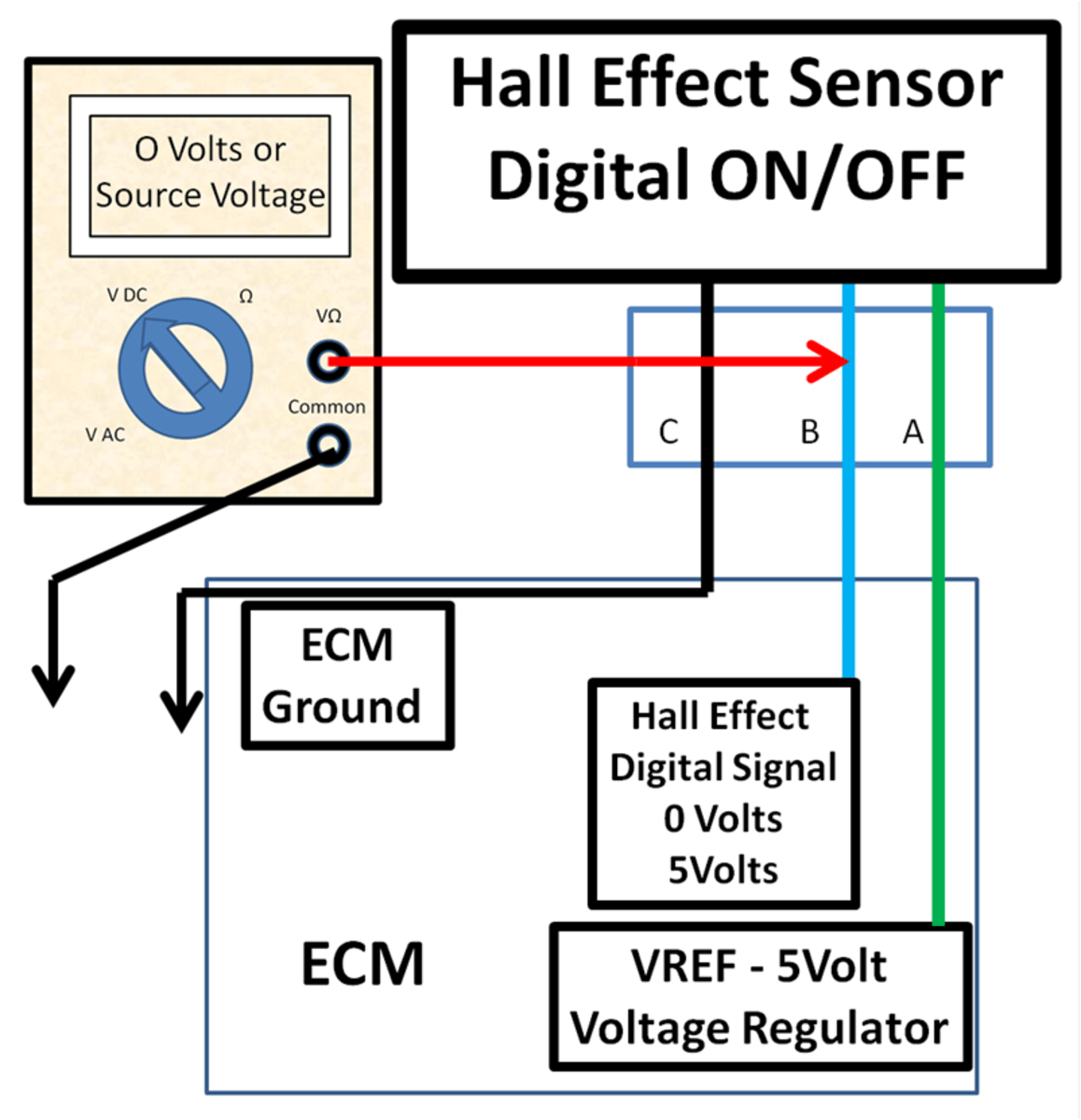
DIY Auto Service Permanent and Hall Effect Sensor Diagnosis and
The circuit diagram shows that the arduino powers up the hall effect sensor, and a single led connects to the arduino’s output. You can use hall effect sensor to make many diy projects such as. The vcc of the sensor is connected to arduino's 5v power pin. Web thus, you can interface your a2144 hall effect sensor accompanied by an.

Hall Effect Sensors Physical Computing
Connect the module’s vcc (voltage) pin to the 5v pin on the arduino. The vcc of the sensor is connected to arduino's 5v power pin. This can be useful for projects where you need to find the rpm of a motor or other movements in a machine. You can use hall effect sensor to make many diy projects such as..
Hall Effect Sensor Wiring - Web tutorial on how to use a hall effect sensor featuring the ss49e linear hall effect ic and arduino uno. The gnd of the sensor is connected to the gnd pin on the arduino. Learn how to expand your project's capabilities with hall effect sensors! Connect the module’s gnd (ground) pin to the gnd pin on the arduino. Web this comprehensive guide will delve into the intricacies of hall effect sensor wiring, providing you with the knowledge and tools to confidently integrate these sensors into your diy projects. Web in this tutorial we cover the hall sensor, a sensor to measure magnetic fields.
Web in this guide, you’ll learn how to set up an arduino hall effect sensor, specifically the us1881, to detect magnetic fields. Full wiring diagram and sketch here: You can use hall effect sensor to make many diy projects such as. Connect the module’s gnd (ground) pin to the gnd pin on the arduino. The gnd of the sensor is connected to the gnd pin on the arduino.
Web With A Hall Sensor, Arduino Projects Can Detect Magnetic Fields.
Connect the analog hall effect sensor module 49e to the arduino board as follows: Learn how to expand your project's capabilities with hall effect sensors! Connect the module’s vcc (voltage) pin to the 5v pin on the arduino. The gnd of the sensor is connected to the gnd pin on the arduino.
Web Thus, You Can Interface Your A2144 Hall Effect Sensor Accompanied By An Arduino Board Via The Wiring Connections Shown In The Circuit Diagram Below:
The circuit diagram shows that the arduino powers up the hall effect sensor, and a single led connects to the arduino’s output. You can use hall effect sensor to make many diy projects such as. Web this comprehensive guide will delve into the intricacies of hall effect sensor wiring, providing you with the knowledge and tools to confidently integrate these sensors into your diy projects. Connect the module’s gnd (ground) pin to the gnd pin on the arduino.
Full Wiring Diagram And Sketch Here:
Connect the module’s out (analog output) pin to an analog input pin on the arduino (e.g., a0). Web may 2, 2022 by techiescience core sme. After we know the fundamentals, we cover two different sensors: Web in this guide, you’ll learn how to set up an arduino hall effect sensor, specifically the us1881, to detect magnetic fields.
Web Interfacing The Hall Effect Sensor With Arduino Is Really Simple.
The vcc of the sensor is connected to arduino's 5v power pin. Web tutorial on how to use a hall effect sensor featuring the ss49e linear hall effect ic and arduino uno. Web hall effect switch or hall effect sensor switch is a switch that turns on when enough magnetic field near the ic. The vout or signal pin of the hall effect sensor is connected to the arduino's interrupt pin (digital pin 2).